Engine zincs replace 2007
(See Systems List on Nevermore's engine pencil-zincs.)
There are two pencil zincs on Nevermore's engine. Both are shown in the Westerbeke engine Parts List "Cooling System" figure on page 220 (and repeated on page 222.) This figure is also on the [web], as is the parts item list that is on our hardcopy pages 221 and 223.
The heat exchanger is REF number 23 (P/N 15799), and the oil cooler is REF #32 (P/N 11518).
Both pencil zincs are shown as REF #33 (P/N 11885). This is a workable part for the heat exchanger, but NOT for the oil cooler, which requires a fatter and possibly shorter pencil, with a larger screw thread radius.
PHOTO DESCRIPTIONS
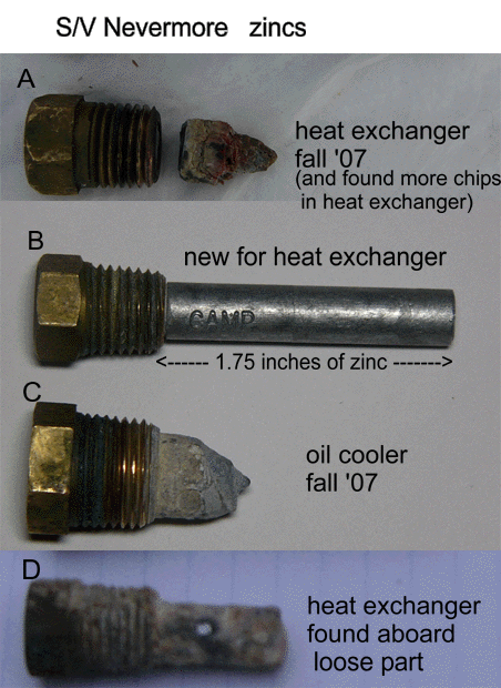
- A: Old pencil zinc removed from the heat exchanger (the heat exchanger moves sea water over cooling tubes which have circulating fresh water, which in turn cools the engine.)
- The little chunk was found inside the heat exchanger, along with several very small (like sand) pieces of zinc (and/or possibly actual sand?)
- B: New pencil zinc installed Fall '07; we found two of these aboard Nevermore in the box of new spare parts.
- C: Old pencil zinc removed from the oil cooler (the oil cooler moves sea water over cooling tubes which have circulating engine oil, the same oil used to lubricate and cool the engine.)
- D: Old pencil zinc found aboard Nevermore; it's the same size as (B), so we assume it was removed by previous owner, but at unknown (to us) time.
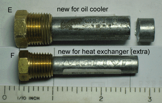
- E: New pencil zinc we bought, ready to be installed in the oil cooler (Jan08); we had to cut down its length (we discuss this below, but note that its original zinc part is longer than the heat exchanger zinc, whereas the oil cooler is smaller diameter than the heat exchanger.)
- F: Another new pencil zinc for the heat exchanger, presented here to show the different size of item E zinc. We bought it (West Marine) to compare to the units we found aboard (see item B.)
COMMENTS and THOUGHTS
- Glossary: (quick-'n'-dirty definitions for tech-newbies interested in the Nevermore fitting-out saga):
- HE or Heat Exchanger : raw seawater is pumped through an outer cylinder at the same time that fresh engine cooling water is circulated through pipes in the cylinder; heat is transferred from the fresh water to the seawater and removed from the engine.
- OC or Oil Cooler : raw seawater is pumped through an outer cylinder (the same water the HE uses), and cools the engine oil which is circulated -- probably via small pipes -- inside the cylinder; the engine oil is cooled.
- zinc, or pencil-zinc : well, start by looking at the pictures B, E and F; consists of a bronze (?) threaded plug and a pencil of zinc which (often) screws into it; when electric currents flow in the salt water in which the pencil is emmersed, the zinc, being the least-noble metal we expect to find around the boat, will become a sacrificial anode, and it, rather than other boat parts, will be eaten away by galvanic corrosion.
- The HE and OC are shown in the "Cooling System" diagram in the engine's Parts List, on page 220 (and repeated on page 222), with the parts list tabulation on pages 221 and 223. (These pages are also on the [web]).
- The HE is REF #23 (P/N 15799) and the OC is REF #32 (P/N 11518). The parts list shows both using pencil zinc REF #33 (P/N 11885) but we see that this part only fits the HE.
- Two pencil-zincs for the HE like Picture B were found aboard; one replaced the Pic A zinc in Fall '07.
- The Pic B zinc is very similar to West Marine's unit. They have 1/4" NPT thread plugs and a 3/8" diameter x 1-3/4" length pencil.
- We don't know whether the Picture B unit is the correct one. We'll discuss later that maybe we want a longer pencil.
- The OC's zinc Pic C, removed from the OC in Fall '07, had no replacement aboard. And the Parts List misidentifies the Westerbeke P/N for it.
- The plug threads and pencil diameter of West Marine's zinc, Pic E (before we cut it shorter), match the Pic C unit and replaced the old Pic C unit.
- The Pic E zinc's plug has 3/8" NPT threads, and the pencil is 1/2" diameter x 2" length.
- With the uncut pencil, we screwed the plug in 3-1/2 turns. We think, but are not sure, that the pencil started bottoming out (the O.D. of the OC's cylinder is about 2-1/8", but there's a built-up female threaded piece about 9/16" extending radially off the cylinder. Looking in the screw hole, we maybe saw some "radiator core" material that the pencil might be hitting (or else it could just be chips of zinc?) The net "theoretical" clearance needed would demand cutting about 1/8 to 1/4" off the zinc, but we cut about 3/8" off (as you can see from the Pic E "cookie" shown with the unit.
- We note that the length of the OC's zinc is more critical than the HE's, because the OC zinc screws in downward from the top of the cylinder. Hence, if the water doesn't fill the OC cylinder, the whole zinc won't be innundated. (But probably our mental image of the water kind of burbling through the OC cylinder, rather than filling it completely, is inspired by the way that seawater burbles out the exhaust port.) At least when the engine isn't running, the water level quite probably DOES drop.
- We've tried to make some sense of the shapes of the corroded pencils of Pics A, C and D.
- The HE's zinc gets screwed in from the underside of the cylinder.
- Pic A's zinc has rotted near the bottom of the cylinder.
- Thom thinks the little pointed piece of zinc, found lying on the bottom of the HE cylinder, should be pictured with its pointy end pointing to the left toward the plug (i.e., pointing down in the HE.) In which case, the water that brought the currents to the zinc would not inundate the zinc part for long periods of time.
- Mentally putting the chunk (rotated 180-degrees) back on Pic A's plug, the end of the zinc away from the plugs in Pics A and D would be approximately the same length. So we can say that some water condition consistently corroded the ENDS of the two plugs. Thom can't imagine it being anything other than the flow of raw water pumped through the HE and OC hitting that end of the zincs. And then the zinc that came to us installed in the HE might have had the little piece eaten off with a shallow pool of water that stayed that way while the boat wasn't used in the months (years(?)) before she came to Boston. And that the Pic D zinc was itself left in too long, but during a time of meaningful usage of the engine, where it lost its end away from the plug.
- The HE's zinc gets screwed in from the underside of the cylinder.
- Questions/mullings:
- I'll bet the little hole visible in Pic D, which is drilled maybe 1/32 to 1/16" into the pencil, provides a gauge of when the zinc should be replaced, assuming of course that it hasn't lost any length.
- Thom has never seen a writeup on how to "check and replace zincs". Specifically, should we use thread tape or goop on the new zincs, since all landsman's directions for NPT connections talk about doing so. But of course, we homemakers usually see this info when doing water or gas work, with higher pressure than Thom imagines in the raw-water path ...
- Research TODOs:
- Order an "official" Westerbeke HE zinc, to see what size it is.
- Ask Westerbeke what length the OC zinc should be (see our "want longest possible" note above.)
- Get a good eye to see what's at the bottom of the OC cylinder.
- Flush, or reverse flush, the HE and OC (probably separately) (one winterizing source says to do this to the HE).
Engine Zincs Replace 2009
We replaced the heat exchanger (HE) zinc in mid-September 2009, and the oil cooler (OC) zinc early December 2009.
Figure B-2009 shows what the 2007 Figure B's new zinc looked like when we removed it mid-Sept 2009.
We had assumed that the HE zinc we found in 2007 when we got Nevermore (Figure A way above) was
so eroded because of lack of service of the boat its last few years with the previous owner.
Alas! We're chagrined to see that we let this zinc erode so far! The time in the water
was from 15 to 17 months, for which the ship's "chief zinc engineer" is much embarrassed!
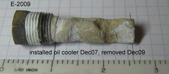
Figure E-2009 shows 2007's Figure E zinc (see way above) as of early Dec 2009. This erosion
appears not to be excessive. However, its shape shows a pattern which shoots down a
theory of wear suggested from the 2007 sample. When we inspected this zinc in Jul '09,
we saw two pits about 2/3 of the way from the screw end, like the point of a drill bit (maybe 5/16")
had been run into the zinc. It looked as though strong streams of water ablated the zinc.
Our original explanation for the pointed stubby end in 2007 (Figure B way above) was
that the zinc spent a lot of time with its water level only up to the place where the point
was left.
Now I'm thinking that the alleged blast of water could have severed the tip of the 2007 zinc
off, and perhaps it is lying in the bottom of the OC cylinder -- at least until it gets eaten
itself by an electrical current. Question: what condition will the place where the zinc tip rests
on the part of the OC assembly made of metal which may get eaten away? And we expect the metal
sheet separating the circulating oil from the cooling water will be redily eaten through
by this electrolysis!?
Engine Zincs Replace 2010
Both the Heat Exchanger and the Oil Cooler zincs were replaced May 2010. No loss of the pencil material was observed, though change of the zinc material was very noticeable. The zincs were not photographed, nor need they have been.


