Engine rewire 12v main sw top broken 101107
From MITNA
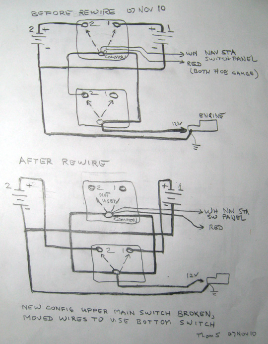
sketch of change to 12-v battery main switches wiring 07Nov10
Notes and Discussion
- The upper main battery switch's handle came apart in our hand. The shaft still turned to allow the switch to visit all 4 of its positions (OFF, Batt #1, BOTH batts, Batt #2, OFF) but one couldn't know what position switch was on was not too apparent by the chunk of bakelite left on, and attached hard, to the shaft of the switch.
- We moved the most important wires from the broken top switch to the bottom switch. (mostly Eric moved, Thom brought up history etc, and both designed.)
- The various functional duties of the switches and wiring are discussed 1-by-1 now:
- The basic switching of 12-volt high current from the batteries to the engine were moved with no change from the top switch to the bottom switch.
- We noted that -- in the old config -- there was a heavy wire jumper between the common terminal of both switches, so that the heavy current to the motor, the lighter current to the Nav Station switches, and the lighter current to whatever is on the red wire were all dispatched from the common of the top switch.
- We obviated the use of the jumpers between the commons to carry the high-current power to the engine.
- We doubled-up the jumpers between the two common terminals, partly because one of them was too hard to take off without breaking its terminal lug, and partly because we could get the extra paralleling we used to get by turning to position #2 the lower battery switch (valid for when we didn't want to use battery #3, which we don't have any more.) (Note that this feature wasn't made part of battery SOPs anyway.)
- Having the connections to the White and Red #08 gauge wire NOT on the same common terminal as the lower (now) switch's common appears to give a more solid connection on the terminal post, even though 3 thick jumpers are attached there. One of the common-to-common jumpers can be removed without any detriment, since we believe the amount of drive going through the White and Red wires is nothing like e.g. engine cranking power.
- Note that some functionality of the wiring is not shown on the diagram, specifically the other wires connected thereto: battery charger to Batt #1 and #2, automatic bilge pump on Batt #1, the smaller red wire on the switch's common terminal, and perhaps others Thom can't think of.
- The basic switching of 12-volt high current from the batteries to the engine were moved with no change from the top switch to the bottom switch.
