Difference between revisions of "Mashnee systems"
(→Sails We Used To Own) |
(→Jib) |
||
| (111 intermediate revisions by 6 users not shown) | |||
| Line 1: | Line 1: | ||
| − | This is an exhaustive list of Mashnee's various subsystems. | + | This is an exhaustive list of '''Mashnee's''' various subsystems. |
= Specifications = | = Specifications = | ||
| Line 13: | Line 13: | ||
=== Shrouds and Spreaders === | === Shrouds and Spreaders === | ||
| − | |||
=== Headstay and Backstay === | === Headstay and Backstay === | ||
| + | === Running Backstays === | ||
| + | |||
| + | Running Backstays: 55', 1/2" double-braid | ||
==Running Rigging== | ==Running Rigging== | ||
| − | === | + | === Main === |
| + | Main Halyard: ~75' 3/8" cored line spliced to ~45' 14' single braid (lengths approximate) | ||
| + | Main Sheet: 90', 9/16" three-strand | ||
| − | + | Shallow Reef Outhaul: 50', 3/8" double-braid | |
| + | Deep Reef Outhaul: 58', double braid | ||
| − | === | + | === Jib === |
| + | Halyard | ||
| + | Secondary Halyard | ||
| − | + | Sheets: 58', 9/16" double-braid | |
| + | Roller furler line | ||
| − | + | Selden Furlex 300s roller furler | |
| − | == | + | === Spinnaker === |
| + | Halyard: ~130' 7/16" cored line with pelican hook. (Length approximate) | ||
| + | Secondary Halyard: ~90' 7/16" cored line spliced to ~33' 1/4" single braid, ending with 6' cored line. (Lengths approximate. Thin section is a hazard as it can jump out of the halyard block sheave and jam.) | ||
| − | + | Sheets: 107', 87' of 3/8" double-braid with 20' of 5/16" single-braid section | |
| + | Tack Outhaul (standard): 75' 1/2" double-braid | ||
| − | + | Tack Outhaul (top-down furler): 45', 40' 1/2" double braid with 5' of 3/8" single-braid section | |
| + | Top-Down Furler line: 50', double-braid | ||
| − | = | + | = Sails = |
| + | == Sails Kept on the Boat== | ||
| − | |||
| − | === | + | ===Mainsail=== |
| + | * Sobstad mainsail, new 2021 (only really used 2022) | ||
| − | === | + | ===Headsails=== |
| + | * working jib (<100%)(~2008) | ||
| + | * 95 (new 2023) | ||
| + | * 140 (new 2022) | ||
| + | * 165 (new 2022) | ||
| + | ===Spinnaker=== | ||
| + | * code zero (black) in red sobstad bag | ||
| + | * Big red (red) | ||
| − | + | == Sails not on the boat== | |
| − | == | + | * reacher (green and white) - left at pavilion as spare |
| − | + | ||
| − | + | ||
| − | + | ||
| − | + | ||
| − | + | ||
| − | + | ||
| − | + | ||
= Deck = | = Deck = | ||
== Winches == | == Winches == | ||
| − | |||
| − | |||
| − | |||
| − | |||
| − | |||
| − | |||
| − | |||
| − | |||
| − | |||
| − | |||
| − | |||
| − | |||
| − | |||
| − | |||
| − | |||
| − | |||
| − | |||
| − | |||
| − | |||
| − | |||
| − | |||
| − | |||
| − | |||
| − | |||
| − | |||
| − | |||
| − | |||
= Machinery = | = Machinery = | ||
| Line 100: | Line 86: | ||
== Power Train == | == Power Train == | ||
| − | |||
| − | |||
=== Engine === | === Engine === | ||
| − | + | 40 HP Volvo D2-40 diesel engine. Installed: 2008. | |
| − | + | ||
| − | + | ||
| − | + | ||
| − | + | ||
| − | + | ||
| − | + | ||
| − | + | === Transmission === | |
| − | |||
| − | + | === Coupler === | |
| − | + | ||
| − | + | ||
| − | + | ||
| − | |||
| − | |||
| − | |||
| − | |||
| − | + | === Stuffing Box === | |
| − | + | ||
| − | + | ||
| − | |||
| − | + | === Propeller === | |
| − | + | 3 blade Gori feathering propeller. [[File:Mashnee_gori_prop.pdf|manual and instructions for GORI propeller]] and [[File:GORI_Manual-15-16_5-Overdrive-Shaft-A4-3.pdf |more detailed, updated manual]] | |
| − | + | ==== Folding the Propeller==== | |
| − | + | Put the gear shift in reverse when the engine is off. This locks the shaft and ensures the propeller folds and does not spin. Then return the lever back into neutral. | |
| − | === | + | ==== Normal Ahead ==== |
| + | If you want to shift from "overdrive" to normal/forward position, the lever will have to be put into neutral when the boat does more than 1 knot ahead until the blades have folded again, then put it in the forward position again. | ||
| + | If the propeller is spinning with the engine in neutral, you must go gently in reverse, while the boat is moving forward. After the propeller has been going in reverse for a few seconds, you can go back to neutral and the propeller will have folded and the shaft stopped. when you back to forward, the propeller will be in normal ahead. | ||
| + | Before leaving the harbor, always check the position of the propeller by means of the boat's tachometer so that the propeller is in the wanted position. | ||
| + | ==== Going Astern ==== | ||
| + | in the reverse position the blades swing 180 degrees opposite the forward position which ensures the same blade leading edge and profile, resulting in high-efficiency. If the boat has not been used in some time, you should shift cautiously between forward and reversed a few times before sailing in order to clean the teeth of the blades and the gears from fouling. | ||
| − | + | ==== Going Ahead in Overdrive ==== | |
| + | The “Overdrive” function is to be used when motoring at a cruising RPM in fair weather or when motorsailing. Overdrive is a second larger pitch achieved by going forward with the propeller blades in the reverse position. The second higher pitch acts like 5th gear in a car and likewise can increase speed and efficiency. | ||
| − | + | In order to position the propeller in forward "overdrive" it is necessary to move the boat astern so that the blades are kept in reverse position when the lever is put into forward. Do not try to make the propeller go from forward to "overdrive" position by quick shifts with the lever when the boat is sailing ahead in the water. When in reverse position, the blades have a 20% higher pitch than forward. when you go forward with the propeller in the reverse position, this higher pitch is kept, enabling overdrive. | |
| + | If you are in standard forward at the higher RPM and want to go into overdrive: | ||
| + | *1. Reduce the engine RPM and put the shift lever into neutral | ||
| + | *2. Go into reverse | ||
| + | *3. Raise the engine RPM several hundred for a few seconds | ||
| + | *4. Reduce the engine RPM and move the shift lever to forward smartly without hesitation You will now be in overdrive. | ||
| + | If you are in overdrive and want to go into standard forward: | ||
| + | *1. Reduce the engine RPM and put the shift lever into neutral | ||
| + | *2. Bump into reverse for a second which stops the shaft immediately | ||
| + | *3. Wait several seconds (shaft should stop rotating), blades fold closed from forward motion and then shift back into forward | ||
| + | *4. This will give you the standard forward position. By bumping into reverse and leaving the engine in neutral for several seconds you are allowing the shaft to stop rotating and the propeller blades to fold closed (action of water flow over the positively geared blades), then when you go back into forward the blades will open in the standard forward position. | ||
| − | + | Often just after leaving the marina slip you may find that the propeller is in Overdrive. This is due to when backing out of the slip and then shifting the into forward position - while the boat was still moving backwards - the blades will be in the overdrive position. Simply put the shift lever into neutral for a few seconds, make sure the shaft stops turning (bump into reverse for a second) and then back into forward and you will be in the standard forward. Many Gori customers use overdrive for the vast majority of their motoring, only using standard forward in conditions that require great thrust and high RPM such as to power through heavy seas or quickly maneuver. | |
| − | + | ||
| − | + | ||
| − | + | ||
| − | + | ||
=== Muffler === | === Muffler === | ||
| − | + | ||
=== Fuel System === | === Fuel System === | ||
| − | + | 20 Gallon diesel fuel tank. | |
| − | + | ||
| − | + | ||
| − | + | ||
| − | + | ||
| − | + | ||
| − | + | ||
| − | + | ||
| − | + | ||
| − | + | ||
| − | + | ||
| − | + | ||
| − | + | When the tank is full, the fuel gauge reads "F". When the tank is 10 gallons down, the fuel gauge reads "E". The gauge seems to be non-linear and should not be relied upon for accurate measurement of the fuel tank. | |
| − | * | + | === Fluids and Filters and Impeller === |
| − | + | * Engine Oil: 15W-40 | |
| − | : | + | * Engine Oil Filter: volvo penta 3840525 |
| − | * | + | * Racor Fuel filter: R12P |
| − | + | * Engine Fuel Filter: Volvo Penta 861477-8 | |
| − | + | ||
| − | + | ||
| − | * | + | |
| − | + | ||
| − | + | ||
| − | + | ||
| − | + | ||
| − | + | ||
| − | + | ||
== Steering == | == Steering == | ||
| Line 194: | Line 153: | ||
=== Helm === | === Helm === | ||
| − | |||
| − | |||
=== Rudder === | === Rudder === | ||
| − | + | ||
| − | + | ||
== Thru-Hulls == | == Thru-Hulls == | ||
| − | + | * [[Media:2023 thru-hull diagram.jpg | Thru-Hull Diagram]] | |
| − | + | ||
| − | + | ||
| − | + | ||
| − | + | ||
| − | + | ||
| − | + | ||
| − | + | ||
| − | + | ||
| − | + | ||
| − | + | ||
| − | + | ||
| − | + | ||
| − | + | ||
| − | + | ||
| − | + | ||
| − | + | ||
| − | + | ||
| − | + | ||
| − | + | ||
== Bilge Pumps == | == Bilge Pumps == | ||
| − | |||
| − | |||
| − | |||
| − | + | === Strum Boxes === | |
| − | |||
| − | |||
| − | |||
| − | |||
| − | |||
| − | |||
| − | |||
| − | |||
| − | |||
| − | |||
| − | |||
| − | |||
| − | |||
| − | |||
| − | |||
| − | |||
| − | |||
| − | |||
| − | |||
| − | |||
| − | |||
| − | |||
| − | |||
| − | |||
| − | |||
| − | |||
| − | |||
| − | |||
| − | |||
| − | |||
| − | |||
| − | |||
== Head == | == Head == | ||
| − | |||
| − | |||
| − | |||
| − | |||
| − | |||
| − | |||
| − | |||
= Electrical = | = Electrical = | ||
| Line 282: | Line 177: | ||
== 12-volt == | == 12-volt == | ||
| − | === | + | === Electric Wiring === |
| − | + | These two documents were provided by Mashnee's restorers: | |
| − | + | * [[Media:mashnee-electric-diagram.jpg | 12V electric wiring diagram]] | |
| − | + | * [[Media:mashnee-electric-system-handout.jpg | Electric system description]] | |
| − | + | === Lighting === | |
| − | + | === Batteries === | |
| − | + | Two batteries run through a battery switch. Batteries are both house and engine; no distinction possible with current wiring. | |
| − | |||
| − | |||
| − | |||
| − | |||
| − | |||
| − | |||
| − | |||
| − | |||
| − | |||
| − | |||
| − | |||
| − | |||
| − | |||
| − | |||
| − | |||
| − | |||
| − | |||
| − | |||
=== Solar Charging === | === Solar Charging === | ||
| + | Yes | ||
| − | |||
| − | === Circuit Breaker | + | === Circuit Breaker Panel ==== |
| − | |||
| − | |||
| − | |||
| − | |||
| − | |||
| − | |||
| − | |||
| − | |||
| − | |||
| − | |||
| − | |||
| − | |||
| − | |||
| − | |||
| − | |||
| − | |||
| − | |||
| − | |||
| − | |||
| − | |||
| − | |||
| − | |||
| − | |||
| − | |||
| − | |||
| − | |||
| − | |||
| − | |||
| − | |||
| − | |||
| − | |||
| − | |||
| − | |||
| − | |||
| − | |||
| − | |||
| − | |||
| − | |||
| − | |||
| − | |||
| − | |||
| − | |||
| − | |||
| − | |||
| − | |||
| − | |||
| − | |||
| − | |||
| − | |||
| − | |||
| − | |||
| − | |||
| − | |||
| − | |||
| − | |||
| − | |||
| − | |||
| − | |||
| − | |||
| − | |||
| − | |||
| − | |||
| − | |||
| − | |||
| − | |||
| − | |||
| − | |||
| − | |||
| − | |||
| − | |||
| − | |||
| − | |||
| − | |||
| − | |||
| − | |||
| − | |||
| − | |||
| − | |||
| − | |||
| − | |||
| − | |||
| − | |||
| − | |||
=== Cabin Lights === | === Cabin Lights === | ||
| − | |||
| − | |||
| − | |||
| − | |||
| − | |||
| − | |||
| − | |||
| − | |||
| − | |||
| − | |||
| − | |||
| − | |||
| − | |||
| − | |||
| − | |||
| − | |||
| − | |||
| − | |||
| − | |||
| − | |||
| − | |||
| − | |||
| − | |||
| − | |||
| − | |||
| − | |||
=== Horn === | === Horn === | ||
| − | |||
| − | + | === Blower === | |
| − | + | ||
| − | |||
| − | |||
| − | |||
| − | |||
=== Navigation Lights === | === Navigation Lights === | ||
| − | + | == Anti-Electrolysis == | |
| − | |||
| − | |||
| − | + | == Lightning Dissipation == | |
| − | + | ||
| − | |||
| − | |||
| − | + | = Electronics = | |
| − | + | ||
| − | + | ||
| − | + | ||
| − | + | ||
| − | + | ||
| − | + | ||
| − | + | B&G System Notes | |
| − | |||
| − | * | + | * Tips: |
| − | * | + | ** Turn on VHF breaker to get AIS targets on chartplotter |
| − | * | + | ** Turn off the chartplotter before turning off breaker |
| − | + | How to: | |
| − | + | * Connect to the H5000 Webserver to adjust settings, perform calibration, etc. | |
| + | ** Connect to wired ethernet connection with your computer | ||
| + | *** Set your laptop to a manually assigned IPv4 for computer of 192.168.0.1 | ||
| + | *** Ensure subnet mask is 255.255.0.0 | ||
| + | **** Go to a web browser and enter 192.168.0.2 | ||
| − | |||
| − | + | * Restore sailing (and other) instruments display on chartplotter | |
| + | ** Press top button (pages/home) | ||
| + | *** Press gear icon on left | ||
| + | **** Press ‘network’ | ||
| + | ***** Press ‘sources’ | ||
| + | ****** Press ‘auto select’ (wait while it sorts things out) | ||
| − | |||
| − | * | + | * Restore ‘boat speed’ indications |
| + | ** Press top button (pages/home) | ||
| + | *** Press gear icon on left | ||
| + | **** Press ‘network’ | ||
| + | ***** Press ‘sources’ | ||
| + | ****** Press ‘boat speed’ | ||
| + | ******* Select: ‘ST200’ | ||
| − | Make | + | * Make AIS targets visible on chartplotter |
| + | ** Press top button (pages/home) | ||
| + | *** On left ribbon: press ‘vessels’ | ||
| + | **** Shows list of targets | ||
| + | ***** Press ‘display all’ to make them visible on chartplotter | ||
| − | + | * Connect system to compass | |
| + | ** Press top button (pages/home) | ||
| + | *** Press gear icon on left | ||
| + | **** Press ‘network’ | ||
| + | ***** Press ‘sources’ | ||
| + | ****** Press <heading? compass?> | ||
| + | ******* Select: precision 9 | ||
| − | |||
| − | |||
| − | |||
| − | |||
| − | |||
| − | |||
| − | |||
| − | |||
| − | + | Unresolved issues | |
| − | + | *CP forgets configuration items, as above | |
| − | + | ||
| − | + | ||
| − | * | + | |
| − | + | ||
| − | + | ||
| − | + | ||
| − | + | ||
| − | + | ||
| − | + | ||
| − | + | ||
| − | + | ||
| − | + | ||
| − | == | + | All the manuals are here: https://www.dropbox.com/sh/l30jp60jf8nvmqk/AAAtzo6MZP3bd7fXsHzRiP9La?dl=0 |
| + | |||
| + | == Chartplotter MFD == | ||
| + | B&G Zeus 3S | ||
| + | * To activate the MOB feature | ||
| + | ** press both the check mark and the x button (next to each other) at the same time | ||
| + | *** This will drop a waypoint and the graphical display will navigate to that | ||
| + | * To clear the MOB | ||
| + | ** Using the hamburger menu (three bars in the top right), stop navigation. Then click on the MOB X waypoint on the chart and delete it | ||
| − | * | + | * To turn on the radar |
| − | * | + | ** Ensure "radar" is turned on in the overlays menu (hamburger menu button and scroll down) |
| − | * | + | ** Then go to the radar options tab and click "Transmit" |
| − | * | + | ** When you're done, either click "Standby" or "Power Off" per your desired behavior |
| − | * | + | |
| − | + | WIFI: B&G Zeus 3s streams both NMEA 183 and NMEA 2000 | |
| + | * Zeus 3s: SSID: <zeus something…> | ||
| + | ** PW: S4XGzxx9 | ||
| + | ** NMEA 183 stream 192.168.76.1 port 10110 | ||
| + | *** Streams AIS targets and instrument readings | ||
| − | + | == B&G H5000 Hercules CPU == | |
| − | + | ||
| − | + | ||
== Wind == | == Wind == | ||
| + | B&G WS310. | ||
| − | + | == Depth Sounder/Log/Water temperature == | |
| − | + | ||
| − | + | ||
| − | + | ST200 speedo and temperature | |
| + | Echosounder for depth | ||
| − | + | == Precision 9 Compass == | |
| − | + | ||
| − | + | ||
| − | == NMEA 2000 network == | + | == NMEA 2000 network == |
| + | There is a standard NMEA 2000 network with most connections behind the false panel in the aft-most port cupboard (above the ice box). The backbone has been extended using .5 meter backbone cable and a drop tee. There is an additional set of connectors in the forward compartment just to port of the mast. There is one free port at the mast. | ||
| − | + | == Raymarine MN-100-2 Solar Powered Wireless Displays == | |
| + | * Associated wireless interface: Raymarine Tacktick T122 located in aft-most port cupboard | ||
| + | ** Connected to 12 volt power | ||
| + | ** Connected to a NMEA2K to NMEA 183 translator: | ||
| + | *** Actisense NGW-1 | ||
| + | *** Translator powered by NMEA 2K network | ||
| − | + | == Radar == | |
| + | B&G Broadband 4G Radar | ||
| − | + | == AIS Transponder == | |
| − | + | ||
| − | + | ||
| − | + | ||
| − | + | ||
| − | + | ||
| − | + | ||
| − | + | * Vesper Marine [https://www2.vespermarine.com/xb8000-ais-transponder XB-8000] Class-B AIS Transponder. As of Aug. 2019, it is installed behind the VHF in the forward compartment. The WiFi network and password are written on the unit. | |
| + | To connect to NMEA 183 stream with AIS targets: 192.168.15.1 port 39150 | ||
| − | + | Pw: PaveTheRiver | |
| + | To connect to NMEA 183 stream with AIS targets: 192.168.15.1 port 39150 | ||
| − | |||
| − | |||
| − | |||
| − | |||
| − | |||
| − | |||
| − | |||
| − | |||
| − | |||
| − | |||
| − | |||
| − | |||
| − | |||
| − | |||
| − | |||
| − | |||
| − | |||
| − | |||
| − | |||
| − | |||
| − | |||
== Radios == | == Radios == | ||
| Line 588: | Line 330: | ||
=== Fixed VHF === | === Fixed VHF === | ||
| − | + | * Uniden UM525 Fixed Mount VHF Marine Radio | |
| − | * | + | * Owner's Manual: [[File:Uniden_UM525_VHF_Radio.pdf]] |
| − | * | + | * MMSI Number: 338236803 (assigned via SeaTow) |
| − | + | ||
| − | + | ||
| − | + | ||
| − | + | ||
| − | + | ||
| − | + | ||
| − | + | ||
| − | + | ||
| − | + | ||
| − | + | ||
| − | + | ||
| − | + | ||
= Magnetic Compasses = | = Magnetic Compasses = | ||
| − | + | There is a magnetic compass which is placed in the starboard cockpit locker. When it is deployed it is mounted on a small brass rail at the foot of the companionway. | |
| − | + | ||
| − | + | ||
| − | + | ||
| − | + | ||
| − | + | ||
| − | + | ||
| − | + | ||
| − | + | ||
| − | + | ||
| − | + | ||
| − | + | ||
| − | + | Note, this compass cannot be trusted. Compasses do not take hard knocks well, and there is no guarantee that its placement is not in a magnetically pathological location. This compass can be used for relative heading hold, e.g. maintaining a number. However, the absolute values are not to be trusted at all. [KDS] | |
| − | + | ||
= Galley = | = Galley = | ||
| Line 626: | Line 344: | ||
== Stove == | == Stove == | ||
| − | + | The stove is an Orico-style alcohol stove. Alcohol does not burn as hot as propane so it takes longer to cook. | |
| − | + | ||
| − | + | ||
| − | + | ||
| − | + | To operate the stove, remove the wooden plate and place it above, where the metal underside will serve as a heat deflector. | |
| − | + | The top of the stove needs to be open to reveal the metal canister underneath. There is a black rubber disk which seals the canister and keeps the alcohol from evaporating. Remove this. | |
| − | + | ||
| − | + | ||
| − | + | Ensure that the stove dial is turned to the on position, and then the stove can be lit with a lighter or match. | |
| − | The | + | The stove is extinguished by turning the dial fully off, and then replacing the rubber disk and the wooden cover. |
| − | + | == Ice Box == | |
| + | * There is a sump under the ice box to collect the meltwater. This sump can be emptied via the salt water foot pump for the sink if the cross-flow valve underneath the sink is switched. The valve has a pointer on it and the pointer must point up (12:00) for sump drain and to the right (3:00) for the salt water intake. | ||
| − | + | [[File:WaterPumpSwitch.jpg|600px|sump drain valve - click to see]] | |
| − | + | ||
| − | + | ||
| − | + | == Utensils == | |
| − | |||
| − | |||
| − | |||
| − | |||
| − | |||
| − | |||
| − | |||
| − | |||
| − | |||
| − | |||
| − | |||
== Fresh Water == | == Fresh Water == | ||
| − | |||
| − | |||
= Safety = | = Safety = | ||
| Line 669: | Line 368: | ||
== Fire Extinguishers == | == Fire Extinguishers == | ||
| − | |||
| − | |||
| − | |||
| − | |||
| − | |||
== PFDs == | == PFDs == | ||
| + | # Spinlock DeckVest Lite 170n, new 2023. Equipped with MOB 1 AIS beacon (exp. 2030) (Replaced a Spinlock 5D, purchased 2015, retired for failed zipper car) | ||
| + | # Spinlock 5D, new 2015. Arm kit replaced March 2023. | ||
| + | # Spinlock 5D, new 2015. Arm kit replaced March 2023. | ||
| + | # Spinlock 6D, new 2022. Equipped with MOB 1 AIS beacon (exp. 2029) | ||
| + | # Spinlock DeckVest Lite 170n, new 2023. Equipped with MOB 1 AIS beacon (exp. 2030). (Replaced a Spinlock 5D, new 2015, retired for torn bladder attachment tab) | ||
| + | # Spinlock 6D, new 2022. Equipped with MOB 1 AIS beacon (exp. 2029) | ||
| + | # Spinlock 6D, new 2022. Equipped with MOB 1 AIS beacon (exp. 2029) | ||
| + | # Spinlock 6D, new 2022. Equipped with MOB 1 AIS beacon (exp. 2029) | ||
| + | # Spinlock 6D, new 2022. Equipped with MOB 1 AIS beacon (exp. 2029) | ||
| − | * | + | * Inflators are UML5 (5D) or Sensor PRO (6D) with 38g cylinders |
| − | + | * All have harnesses built-in | |
| − | + | ||
| − | * | + | |
| − | + | ||
| − | + | ||
== Throwables == | == Throwables == | ||
| − | + | ||
| − | + | ||
== Harnesses, Jacklines, Tethers == | == Harnesses, Jacklines, Tethers == | ||
| − | + | * 8 tethers, 3 new as of 2022, 3 new as of 2023. 2023 set are West Marine Racing Series Double Safety Tethers. | |
| − | * | + | * 4x jacklines |
| − | * | + | |
| − | + | ||
== Visual Distress Signals == | == Visual Distress Signals == | ||
| − | |||
| − | |||
| − | |||
| − | |||
| − | |||
| − | |||
| − | |||
Latest revision as of 14:55, 26 February 2024
This is an exhaustive list of Mashnee's various subsystems.
Contents
Specifications
Anchors
Rigging
Mast and Boom
Standing Rigging
Shrouds and Spreaders
Headstay and Backstay
Running Backstays
Running Backstays: 55', 1/2" double-braid
Running Rigging
Main
Main Halyard: ~75' 3/8" cored line spliced to ~45' 14' single braid (lengths approximate)
Main Sheet: 90', 9/16" three-strand
Shallow Reef Outhaul: 50', 3/8" double-braid
Deep Reef Outhaul: 58', double braid
Jib
Halyard
Secondary Halyard
Sheets: 58', 9/16" double-braid
Roller furler line
Selden Furlex 300s roller furler
Spinnaker
Halyard: ~130' 7/16" cored line with pelican hook. (Length approximate)
Secondary Halyard: ~90' 7/16" cored line spliced to ~33' 1/4" single braid, ending with 6' cored line. (Lengths approximate. Thin section is a hazard as it can jump out of the halyard block sheave and jam.)
Sheets: 107', 87' of 3/8" double-braid with 20' of 5/16" single-braid section
Tack Outhaul (standard): 75' 1/2" double-braid
Tack Outhaul (top-down furler): 45', 40' 1/2" double braid with 5' of 3/8" single-braid section
Top-Down Furler line: 50', double-braid
Sails
Sails Kept on the Boat
Mainsail
- Sobstad mainsail, new 2021 (only really used 2022)
Headsails
- working jib (<100%)(~2008)
- 95 (new 2023)
- 140 (new 2022)
- 165 (new 2022)
Spinnaker
- code zero (black) in red sobstad bag
- Big red (red)
Sails not on the boat
- reacher (green and white) - left at pavilion as spare
Deck
Winches
Machinery
Power Train
Engine
40 HP Volvo D2-40 diesel engine. Installed: 2008.
Transmission
Coupler
Stuffing Box
Propeller
3 blade Gori feathering propeller. File:Mashnee gori prop.pdf and File:GORI Manual-15-16 5-Overdrive-Shaft-A4-3.pdf
Folding the Propeller
Put the gear shift in reverse when the engine is off. This locks the shaft and ensures the propeller folds and does not spin. Then return the lever back into neutral.
Normal Ahead
If you want to shift from "overdrive" to normal/forward position, the lever will have to be put into neutral when the boat does more than 1 knot ahead until the blades have folded again, then put it in the forward position again. If the propeller is spinning with the engine in neutral, you must go gently in reverse, while the boat is moving forward. After the propeller has been going in reverse for a few seconds, you can go back to neutral and the propeller will have folded and the shaft stopped. when you back to forward, the propeller will be in normal ahead. Before leaving the harbor, always check the position of the propeller by means of the boat's tachometer so that the propeller is in the wanted position.
Going Astern
in the reverse position the blades swing 180 degrees opposite the forward position which ensures the same blade leading edge and profile, resulting in high-efficiency. If the boat has not been used in some time, you should shift cautiously between forward and reversed a few times before sailing in order to clean the teeth of the blades and the gears from fouling.
Going Ahead in Overdrive
The “Overdrive” function is to be used when motoring at a cruising RPM in fair weather or when motorsailing. Overdrive is a second larger pitch achieved by going forward with the propeller blades in the reverse position. The second higher pitch acts like 5th gear in a car and likewise can increase speed and efficiency.
In order to position the propeller in forward "overdrive" it is necessary to move the boat astern so that the blades are kept in reverse position when the lever is put into forward. Do not try to make the propeller go from forward to "overdrive" position by quick shifts with the lever when the boat is sailing ahead in the water. When in reverse position, the blades have a 20% higher pitch than forward. when you go forward with the propeller in the reverse position, this higher pitch is kept, enabling overdrive. If you are in standard forward at the higher RPM and want to go into overdrive:
- 1. Reduce the engine RPM and put the shift lever into neutral
- 2. Go into reverse
- 3. Raise the engine RPM several hundred for a few seconds
- 4. Reduce the engine RPM and move the shift lever to forward smartly without hesitation You will now be in overdrive.
If you are in overdrive and want to go into standard forward:
- 1. Reduce the engine RPM and put the shift lever into neutral
- 2. Bump into reverse for a second which stops the shaft immediately
- 3. Wait several seconds (shaft should stop rotating), blades fold closed from forward motion and then shift back into forward
- 4. This will give you the standard forward position. By bumping into reverse and leaving the engine in neutral for several seconds you are allowing the shaft to stop rotating and the propeller blades to fold closed (action of water flow over the positively geared blades), then when you go back into forward the blades will open in the standard forward position.
Often just after leaving the marina slip you may find that the propeller is in Overdrive. This is due to when backing out of the slip and then shifting the into forward position - while the boat was still moving backwards - the blades will be in the overdrive position. Simply put the shift lever into neutral for a few seconds, make sure the shaft stops turning (bump into reverse for a second) and then back into forward and you will be in the standard forward. Many Gori customers use overdrive for the vast majority of their motoring, only using standard forward in conditions that require great thrust and high RPM such as to power through heavy seas or quickly maneuver.
Muffler
Fuel System
20 Gallon diesel fuel tank.
When the tank is full, the fuel gauge reads "F". When the tank is 10 gallons down, the fuel gauge reads "E". The gauge seems to be non-linear and should not be relied upon for accurate measurement of the fuel tank.
Fluids and Filters and Impeller
- Engine Oil: 15W-40
- Engine Oil Filter: volvo penta 3840525
- Racor Fuel filter: R12P
- Engine Fuel Filter: Volvo Penta 861477-8
Steering
Helm
Rudder
Thru-Hulls
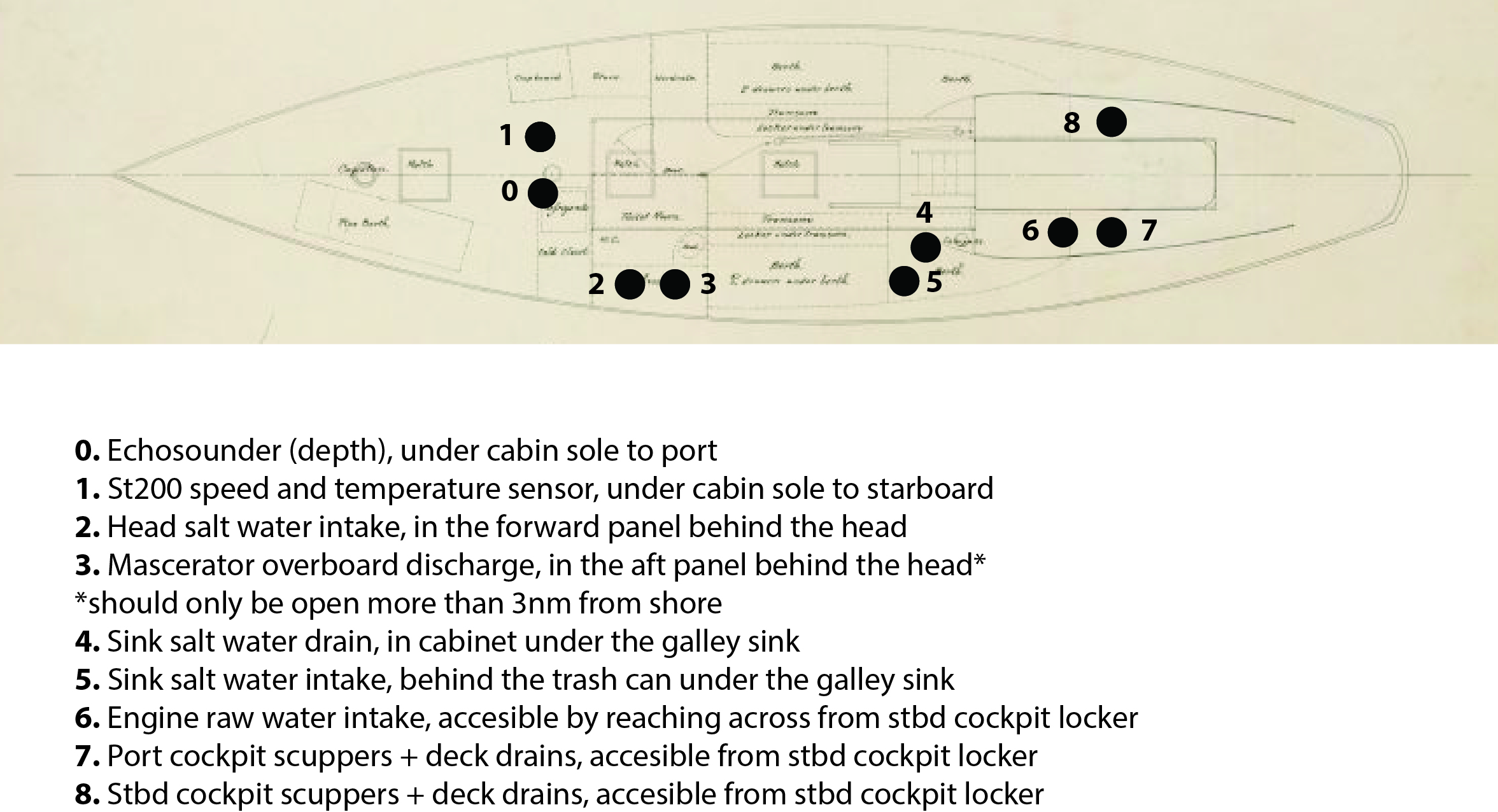
Bilge Pumps
Strum Boxes
Head
Electrical
12-volt
Electric Wiring
These two documents were provided by Mashnee's restorers:
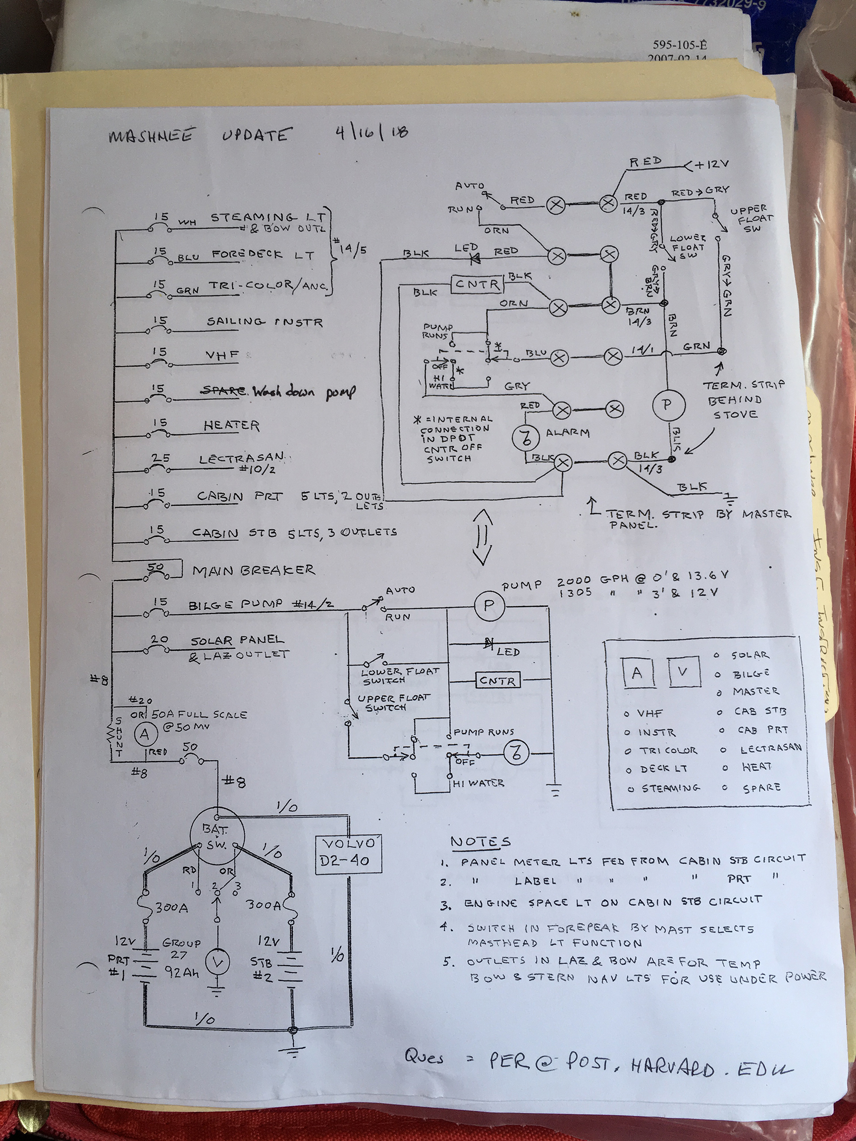
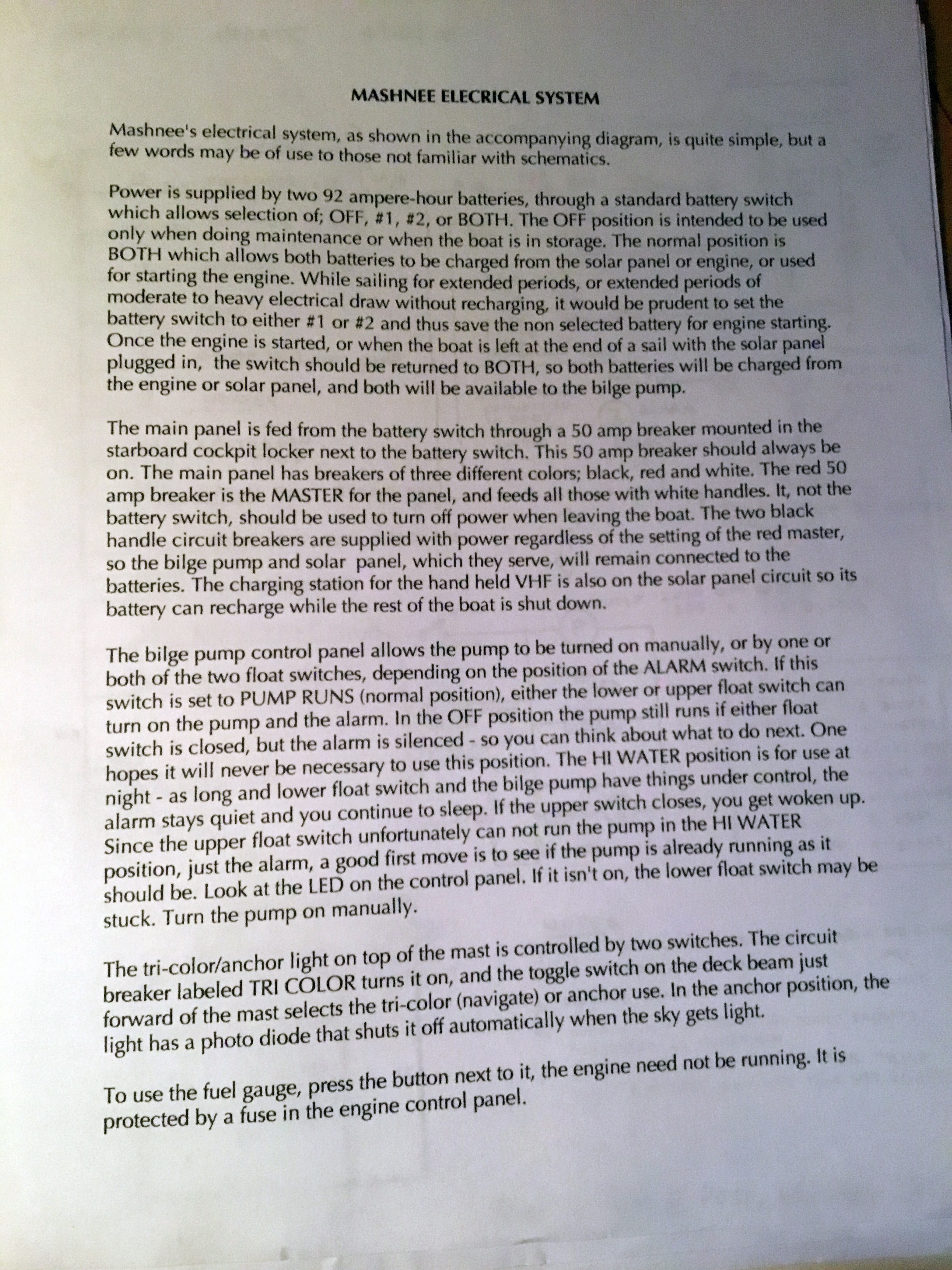
Lighting
Batteries
Two batteries run through a battery switch. Batteries are both house and engine; no distinction possible with current wiring.
Solar Charging
Yes
Circuit Breaker Panel =
Cabin Lights
Horn
Blower
Anti-Electrolysis
Lightning Dissipation
Electronics
B&G System Notes
- Tips:
- Turn on VHF breaker to get AIS targets on chartplotter
- Turn off the chartplotter before turning off breaker
How to:
- Connect to the H5000 Webserver to adjust settings, perform calibration, etc.
- Connect to wired ethernet connection with your computer
- Set your laptop to a manually assigned IPv4 for computer of 192.168.0.1
- Ensure subnet mask is 255.255.0.0
- Go to a web browser and enter 192.168.0.2
- Connect to wired ethernet connection with your computer
- Restore sailing (and other) instruments display on chartplotter
- Press top button (pages/home)
- Press gear icon on left
- Press ‘network’
- Press ‘sources’
- Press ‘auto select’ (wait while it sorts things out)
- Press ‘sources’
- Press ‘network’
- Press gear icon on left
- Press top button (pages/home)
- Restore ‘boat speed’ indications
- Press top button (pages/home)
- Press gear icon on left
- Press ‘network’
- Press ‘sources’
- Press ‘boat speed’
- Select: ‘ST200’
- Press ‘boat speed’
- Press ‘sources’
- Press ‘network’
- Press gear icon on left
- Press top button (pages/home)
- Make AIS targets visible on chartplotter
- Press top button (pages/home)
- On left ribbon: press ‘vessels’
- Shows list of targets
- Press ‘display all’ to make them visible on chartplotter
- Shows list of targets
- On left ribbon: press ‘vessels’
- Press top button (pages/home)
- Connect system to compass
- Press top button (pages/home)
- Press gear icon on left
- Press ‘network’
- Press ‘sources’
- Press <heading? compass?>
- Select: precision 9
- Press <heading? compass?>
- Press ‘sources’
- Press ‘network’
- Press gear icon on left
- Press top button (pages/home)
Unresolved issues
- CP forgets configuration items, as above
All the manuals are here: https://www.dropbox.com/sh/l30jp60jf8nvmqk/AAAtzo6MZP3bd7fXsHzRiP9La?dl=0
Chartplotter MFD
B&G Zeus 3S
- To activate the MOB feature
- press both the check mark and the x button (next to each other) at the same time
- This will drop a waypoint and the graphical display will navigate to that
- press both the check mark and the x button (next to each other) at the same time
- To clear the MOB
- Using the hamburger menu (three bars in the top right), stop navigation. Then click on the MOB X waypoint on the chart and delete it
- To turn on the radar
- Ensure "radar" is turned on in the overlays menu (hamburger menu button and scroll down)
- Then go to the radar options tab and click "Transmit"
- When you're done, either click "Standby" or "Power Off" per your desired behavior
WIFI: B&G Zeus 3s streams both NMEA 183 and NMEA 2000
- Zeus 3s: SSID: <zeus something…>
- PW: S4XGzxx9
- NMEA 183 stream 192.168.76.1 port 10110
- Streams AIS targets and instrument readings
B&G H5000 Hercules CPU
Wind
B&G WS310.
Depth Sounder/Log/Water temperature
ST200 speedo and temperature Echosounder for depth
Precision 9 Compass
NMEA 2000 network
There is a standard NMEA 2000 network with most connections behind the false panel in the aft-most port cupboard (above the ice box). The backbone has been extended using .5 meter backbone cable and a drop tee. There is an additional set of connectors in the forward compartment just to port of the mast. There is one free port at the mast.
Raymarine MN-100-2 Solar Powered Wireless Displays
- Associated wireless interface: Raymarine Tacktick T122 located in aft-most port cupboard
- Connected to 12 volt power
- Connected to a NMEA2K to NMEA 183 translator:
- Actisense NGW-1
- Translator powered by NMEA 2K network
Radar
B&G Broadband 4G Radar
AIS Transponder
- Vesper Marine XB-8000 Class-B AIS Transponder. As of Aug. 2019, it is installed behind the VHF in the forward compartment. The WiFi network and password are written on the unit.
To connect to NMEA 183 stream with AIS targets: 192.168.15.1 port 39150
Pw: PaveTheRiver To connect to NMEA 183 stream with AIS targets: 192.168.15.1 port 39150
Radios
Fixed VHF
- Uniden UM525 Fixed Mount VHF Marine Radio
- Owner's Manual: File:Uniden UM525 VHF Radio.pdf
- MMSI Number: 338236803 (assigned via SeaTow)
Magnetic Compasses
There is a magnetic compass which is placed in the starboard cockpit locker. When it is deployed it is mounted on a small brass rail at the foot of the companionway.
Note, this compass cannot be trusted. Compasses do not take hard knocks well, and there is no guarantee that its placement is not in a magnetically pathological location. This compass can be used for relative heading hold, e.g. maintaining a number. However, the absolute values are not to be trusted at all. [KDS]
Galley
Stove
The stove is an Orico-style alcohol stove. Alcohol does not burn as hot as propane so it takes longer to cook.
To operate the stove, remove the wooden plate and place it above, where the metal underside will serve as a heat deflector.
The top of the stove needs to be open to reveal the metal canister underneath. There is a black rubber disk which seals the canister and keeps the alcohol from evaporating. Remove this.
Ensure that the stove dial is turned to the on position, and then the stove can be lit with a lighter or match.
The stove is extinguished by turning the dial fully off, and then replacing the rubber disk and the wooden cover.
Ice Box
- There is a sump under the ice box to collect the meltwater. This sump can be emptied via the salt water foot pump for the sink if the cross-flow valve underneath the sink is switched. The valve has a pointer on it and the pointer must point up (12:00) for sump drain and to the right (3:00) for the salt water intake.

Utensils
Fresh Water
Safety
Fire Extinguishers
PFDs
- Spinlock DeckVest Lite 170n, new 2023. Equipped with MOB 1 AIS beacon (exp. 2030) (Replaced a Spinlock 5D, purchased 2015, retired for failed zipper car)
- Spinlock 5D, new 2015. Arm kit replaced March 2023.
- Spinlock 5D, new 2015. Arm kit replaced March 2023.
- Spinlock 6D, new 2022. Equipped with MOB 1 AIS beacon (exp. 2029)
- Spinlock DeckVest Lite 170n, new 2023. Equipped with MOB 1 AIS beacon (exp. 2030). (Replaced a Spinlock 5D, new 2015, retired for torn bladder attachment tab)
- Spinlock 6D, new 2022. Equipped with MOB 1 AIS beacon (exp. 2029)
- Spinlock 6D, new 2022. Equipped with MOB 1 AIS beacon (exp. 2029)
- Spinlock 6D, new 2022. Equipped with MOB 1 AIS beacon (exp. 2029)
- Spinlock 6D, new 2022. Equipped with MOB 1 AIS beacon (exp. 2029)
- Inflators are UML5 (5D) or Sensor PRO (6D) with 38g cylinders
- All have harnesses built-in
Throwables
Harnesses, Jacklines, Tethers
- 8 tethers, 3 new as of 2022, 3 new as of 2023. 2023 set are West Marine Racing Series Double Safety Tethers.
- 4x jacklines